Flashing the eMMC of a Radxa Rock Pi 4B Plus

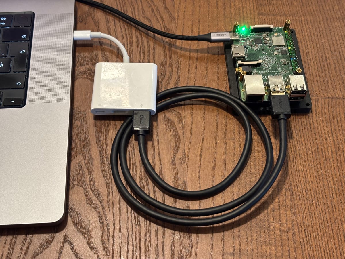
Single-board computers are often discussed through the lens of the Raspberry Pi, but many alternatives use different processors, boot methods, storage layouts, and recovery tools. Radxa's ROCK Pi 4B+ is a good example. It combines an RK3399-family processor with Gigabit Ethernet, USB 3.0, PCIe expansion, and onboard eMMC storage, making it useful for small servers, embedded projects, and other homelab experiments.
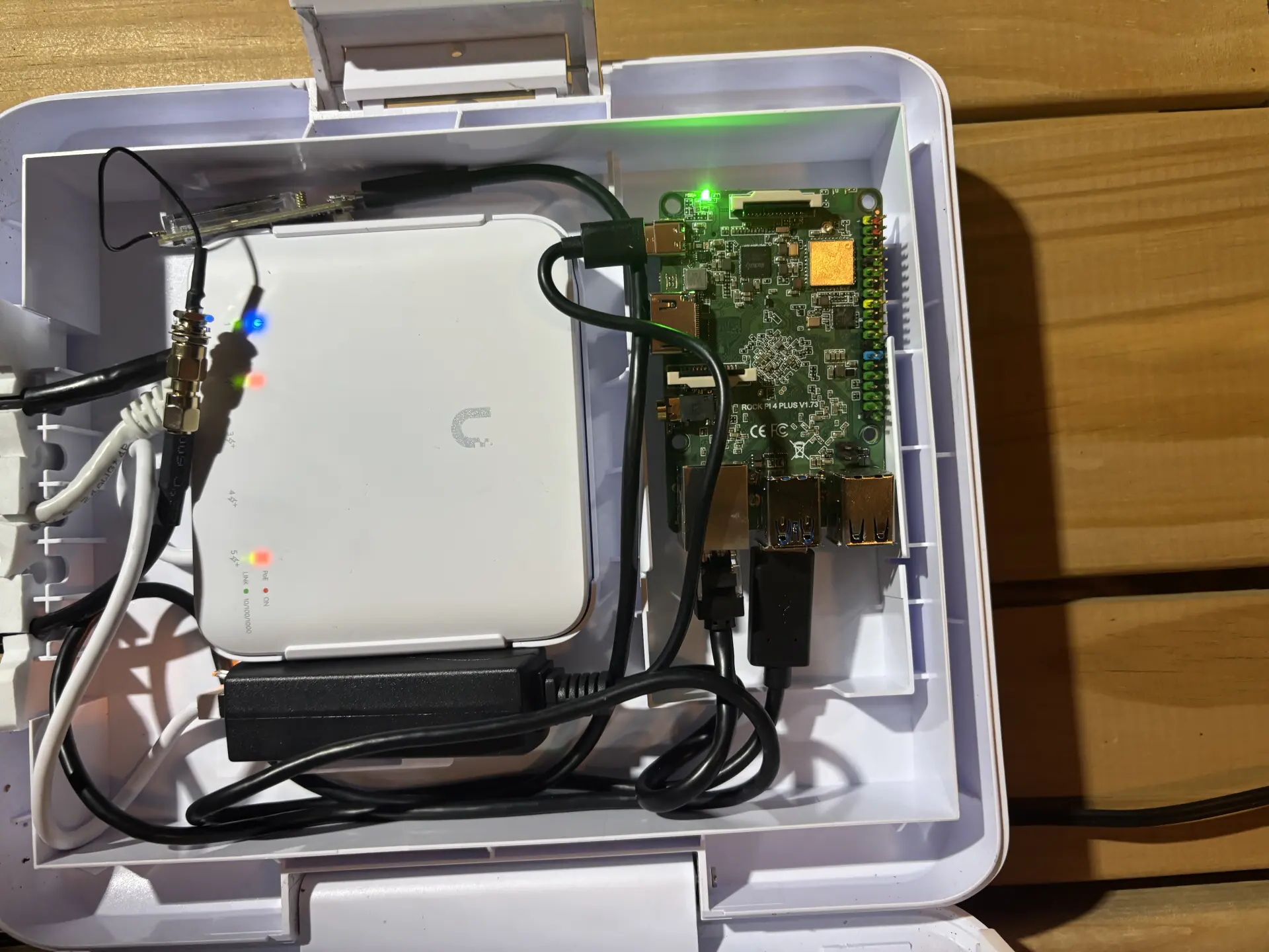
That onboard eMMC is one of the board's more useful features because it allows the ROCK Pi 4B+ to run without relying on a microSD card. MicroSD cards are convenient and inexpensive, but they are also more prone to wear and failure in systems that perform frequent writes or run continuously. The tradeoff is that soldered eMMC cannot simply be removed and inserted into another computer, increasing the complexity of the setup.
The process of flashing the eMMC is straightforward once the hardware is understood, but several small details can make it unnecessarily frustrating. This article explains the relevant hardware, the flashing process, and the specific details required for a successful eMMC installation.
The ROCK Pi 4B+
The ROCK Pi 4B+ is a single-board computer from Radxa built around Rockchip's RK3399 family. It sits in the same broad class of compact ARM computers as the Raspberry Pi, but uses a different processor platform, boot process, and set of board-specific tools. The 4B+ includes Gigabit Ethernet, USB 3.0, PCIe expansion, a 40-pin GPIO header, and onboard eMMC storage, making it useful for small servers, embedded systems, and other homelab projects.
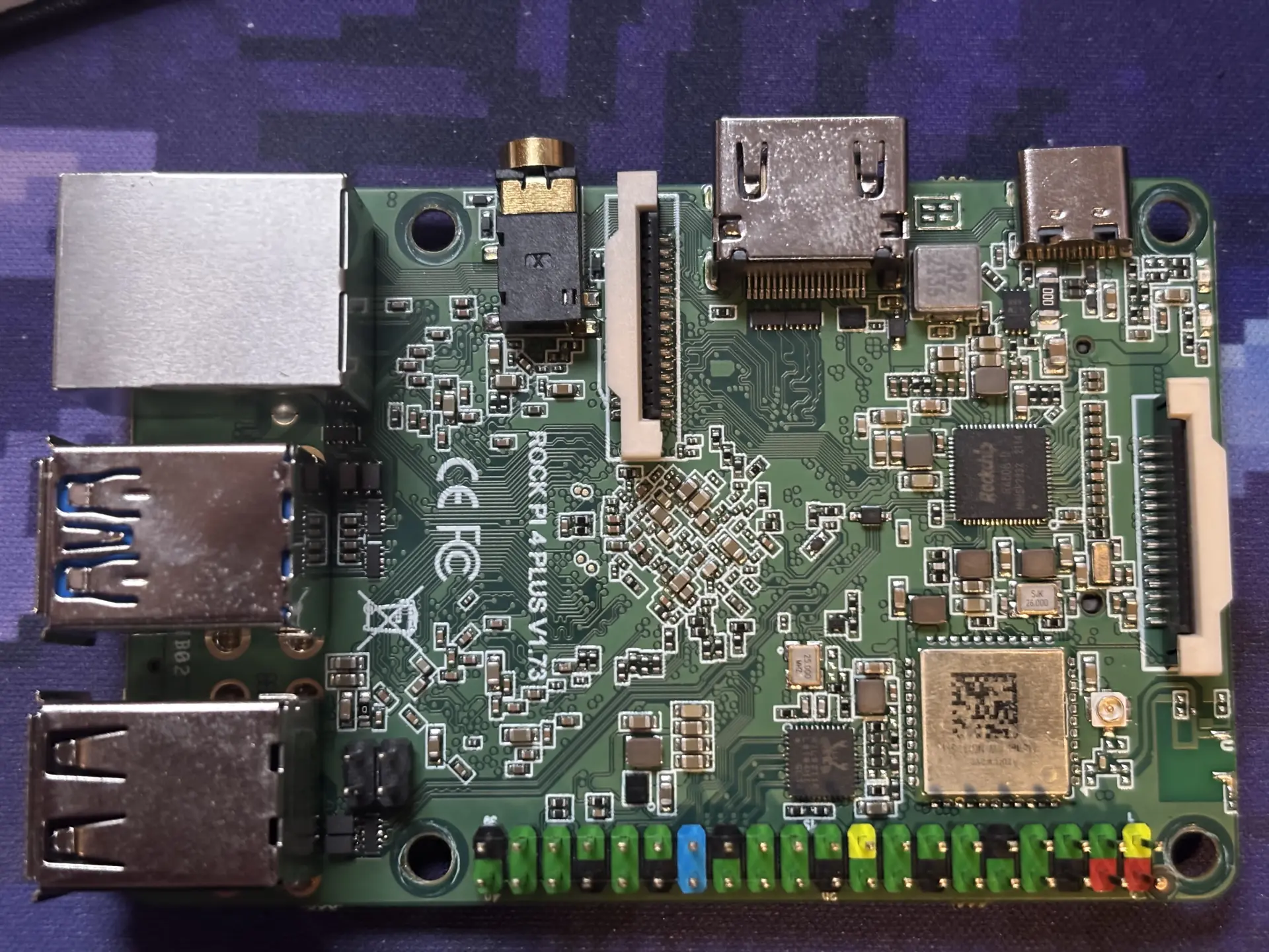
The onboard eMMC is one of its more useful differences from a typical Raspberry Pi setup. Instead of relying entirely on removable microSD storage, the ROCK Pi 4B+ can boot from flash storage soldered directly to the board. That is useful for systems expected to run continuously, where microSD cards can become a reliability concern over time. It also changes how an operating system is installed., since the eMMC cannot simply be removed and flashed in another computer.
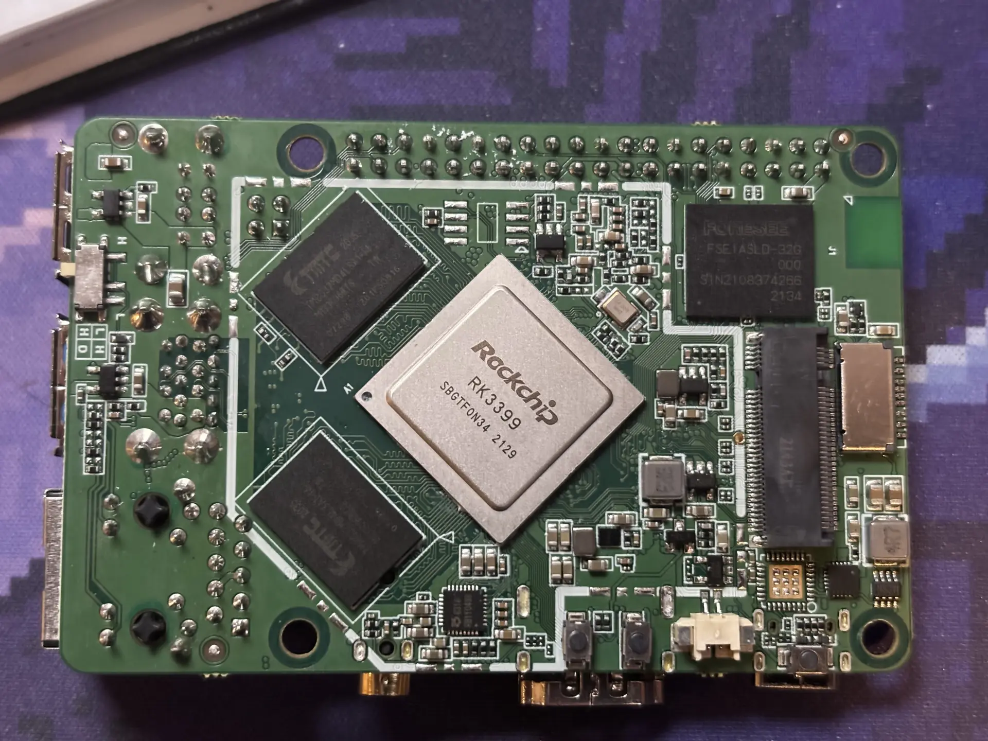
Technodabbler's interest in the ROCK Pi 4B+ started with a Reddit post advertising a batch of the boards at an unusually low price. In the current hardware market, the cost was difficult to ignore, especially for a board with onboard storage, Ethernet, USB, PCIe, and accessible GPIO. Even with only 2 GB of RAM, the ROCK Pi 4B+ looked well suited to experiments involving robotics, wireless communication, sensors, and other projects that benefit more from physical I/O than from desktop-class performance.
What Is Needed to Flash the eMMC
The first challenge in using the ROCK Pi 4B+ is setting it up. The board can be flashed by first booting from a microSD card and then writing the operating system to the onboard eMMC. That approach had mixed results during testing, however. Since Technodabbler purchased eight of these boards, having a repeatable process was more useful than relying on a method that worked inconsistently. Flashing directly over USB through the special "Maskrom" mode became the preferred approach.
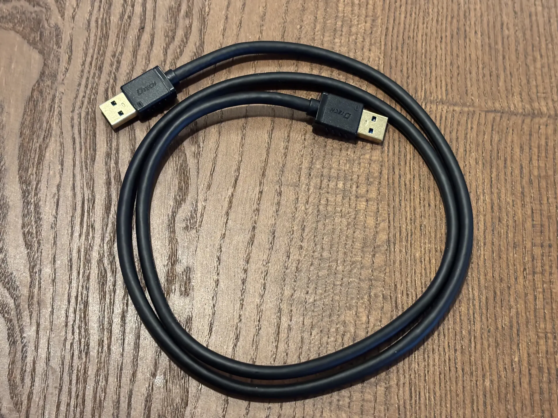
The hardware requirements are modest but specific. A proper USB-A male to USB-A male data cable is needed between the host computer and the ROCK Pi 4B+. This cable is quite usual, so don't expect to have one lying around. USB-C to USB-A cables, including known-good data cables, did not work reliably during testing. The cable also must be connected to the upper blue USB 3.0 port, which is the OTG-capable port used for recovery.
On the host computer, three pieces of software are needed. The first is rkdeveloptool, which provides the interface to the Rockchip processor and the board's storage while it is in Maskrom mode. On Ubuntu 22.10 and later, Radxa documents installation with:
sudo apt-get install rkdeveloptoolOther Linux distributions and macOS use slightly different installation methods. Radxa maintains instructions for all three platforms. For Windows users, you'll need and entirely different tool.


The latest loaders for the ROCK Pi 4B+ can be found on Radxa's download page.
The second requirement is the Rockchip loader, a piece of software uploaded to the processor before the eMMC image is written and prepares the hardware for the flashing operation. The lastest loaders for the ROCK4 family, including boards based on the RK3399, RK3399-T, and Rockchip OP1, can be found here.
 radxa-build
The latest Linux images for the ROCK Pi 4B+ can be found on GitHub.
Finally, an operating system image built for the ROCK Pi 4B+ is required. rkdeveloptool writes the image directly to the onboard eMMC and does not automatically decompress compressed downloads, so files distributed as .xz, .gz, or similar archives need to be extracted before flashing. The latest debian image for the ROCK Pi 4B+ can be found on Github.
Flashing the eMMC
The direct flashing method relies on Rockchip's Maskrom mode, a low-level recovery state built into the processor. The name comes from the mask ROM inside the chip, a small block of read-only code created as part of the processor itself during manufacturing. Because that code does not depend on the contents of the eMMC, it remains available even if the normal bootloader is missing or the storage has been erased. In Maskrom mode, the processor exposes a USB interface that rkdeveloptool can use to communicate with the board and write to its storage.
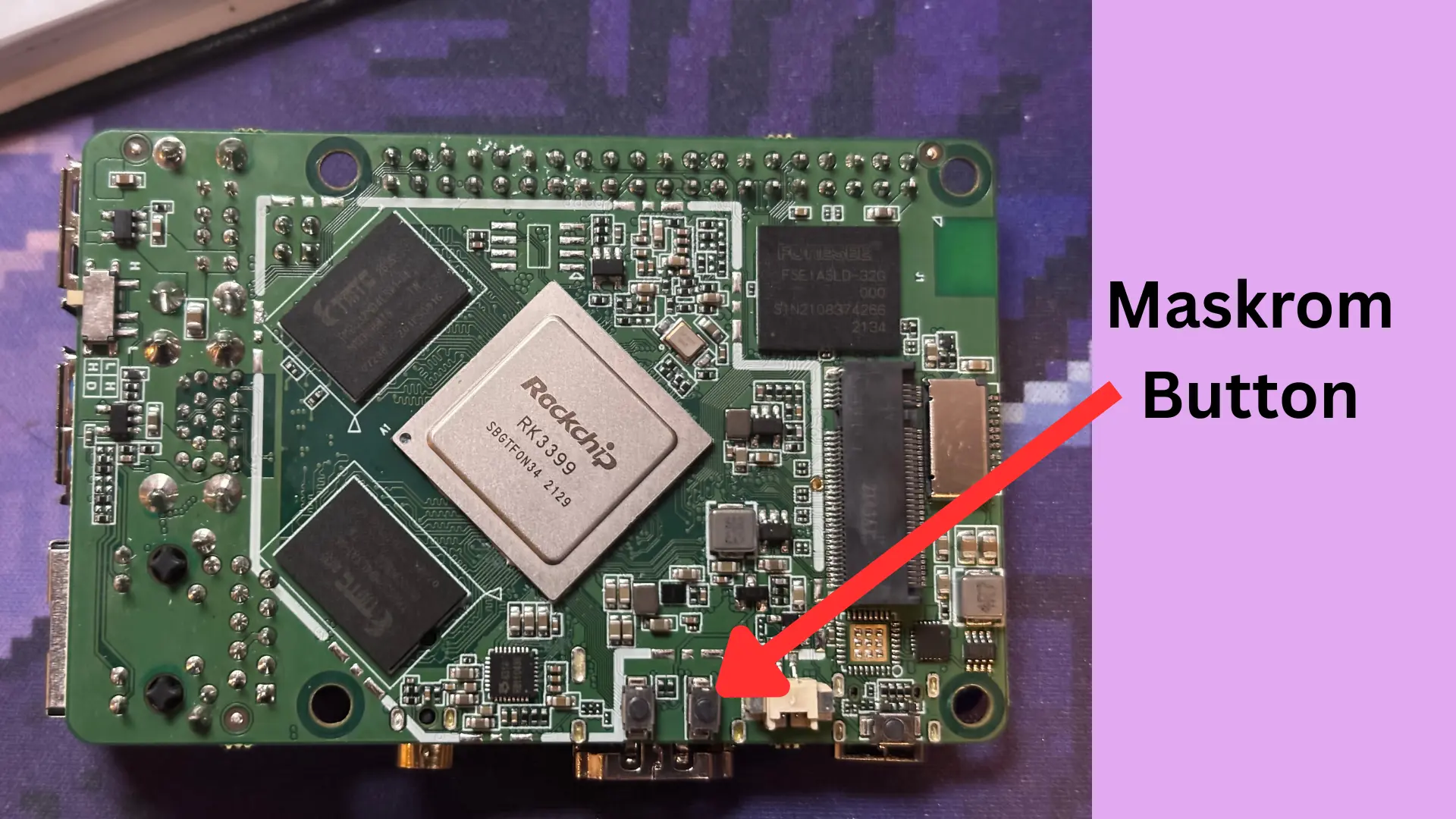
On the ROCK Pi 4B+, entering Maskrom mode requires the dedicated Maskrom button. The button is small, not clearly labeled, and can be difficult to see once a heatsink is installed. With the board powered down and any microSD card removed (this is really important), hold the Maskrom button while connecting the board to USB-C power. Wait three seconds, then release the button. You can how connect the USB-A to USB-A data cable to the host computer.
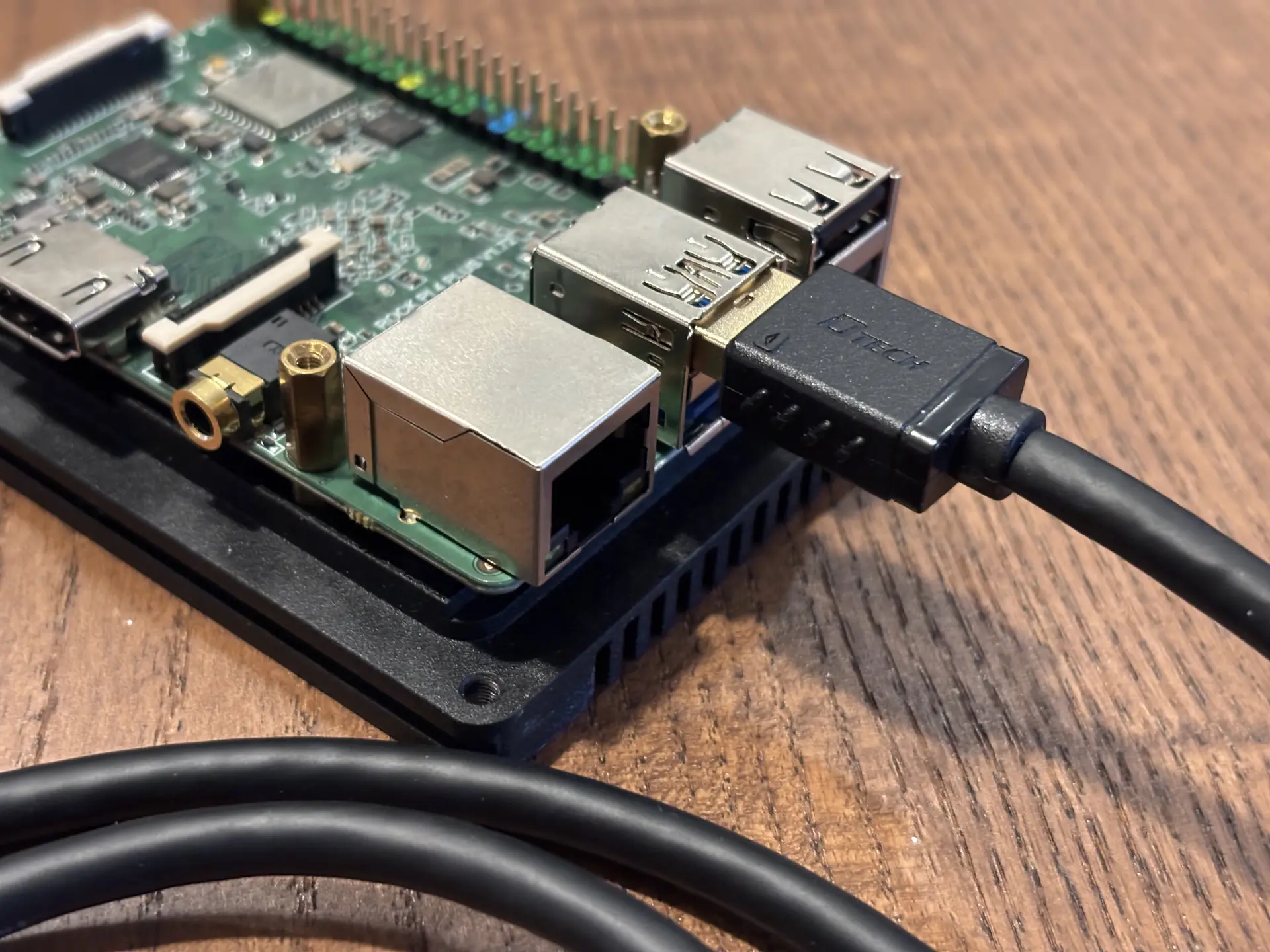
Note that of the two blue USB 3.0 Type-A ports, only the upper blue port is used for the OTG recovery connection. The lower blue port is a conventional host port and will not work for Maskrom flashing.
Once connected, the first step is to confirm that the board is actually in Maskrom mode:
rkdeveloptool ldA successful connection should return something similar to:
DevNo=1 Vid=0x2207,Pid=0x330c,LocationID=201 MaskromThe LocationID may vary between systems, but the important part is the final Maskrom state. That confirms that the Rockchip processor is visible over USB and ready for low-level access.
The RK3399 loader can then be uploaded:
rkdeveloptool db rk3399_loader_v1.27.126.binA successful upload returns:
Downloading bootloader succeeded.The operating system image can then be written directly to the eMMC, starting at LBA 0:
rkdeveloptool wl 0 rock-pi-4b-plus_bookworm_kde_r5.output_512.imgWhen the write completes, rkdeveloptool should report:
Write LBA from file (100%)The final step is to reset the board:
rkdeveloptool rdAfter the reset, disconnect the recovery USB cable and power the ROCK Pi normally. With no microSD card installed, the board should attempt to boot from the newly written eMMC. The default user is "rock" and the corresponding password is "rock".
Not the Easiest Setup
Even with good documentation available, flashing the ROCK Pi 4B+ eMMC took more time than expected. To be fair, the warnings were already there. The process depends on a few board-specific details that are easy to miss, particularly the Maskrom button, the correct USB cable, and the correct USB port.
Once those gotchas are out of the way, the actual flashing process is fairly simple for anyone comfortable working at the command line. The result is also worth the effort. An SBC that boots from onboard eMMC is generally a better fit for long-running projects than one that depends on microSD storage, particularly when reliability matters.
Have you run into similar board-specific quirks when flashing an SBC, or found a more reliable way to install an operating system to eMMC? Share the experience in the comments.
For another Technodabbler project built around inexpensive single-board hardware and wireless experimentation, take a look our exploration of the Lora protocal.